The basics of IoT: its concepts, key applications, and how to set up Arduino or ESP32 boards to blink LEDs and read sensor data in your first IoT lab.
What Is the Internet of Things (IoT)?
The Internet of Things (IoT) refers to a vast network of interconnected devices that communicate and share data with minimal or no human intervention. These “things” include everyday objects such as watches, thermostats, light bulbs, and factory machines embedded with sensors, processors, and connectivity modules.
IoT makes our world smarter and more responsive by enabling machines to sense, analyze, and act in real time. When combined with cloud platforms and artificial intelligence, IoT systems transform raw data into meaningful actions.
Why IoT Matters in Today’s World
IoT is reshaping every major sector:
- Smart Homes: Devices like Alexa, Google Nest, and smart thermostats automate daily tasks.
- Healthcare: Wearables monitor heart rate, sleep, and physical activity remotely.
- Industry 4.0: Sensors track machine health to reduce downtime and improve efficiency.
- Agriculture: Smart irrigation and soil sensors optimize water and fertilizer usage.
- Smart Cities: Connected streetlights and traffic systems reduce energy consumption and congestion.
By 2030, experts estimate over 25 billion connected devices, powering a trillion-dollar global ecosystem.
Core Concepts of IoT
| Concept | Description |
|---|---|
| Device Layer | Physical objects equipped with sensors/actuators that collect or act on data. |
| Connectivity Layer | Networks like Wi-Fi, Bluetooth, or LoRaWAN that transmit data. |
| Cloud Layer | Storage and analytics platforms processing data at scale. |
| Application Layer | Dashboards, alerts, or automation systems visible to users. |
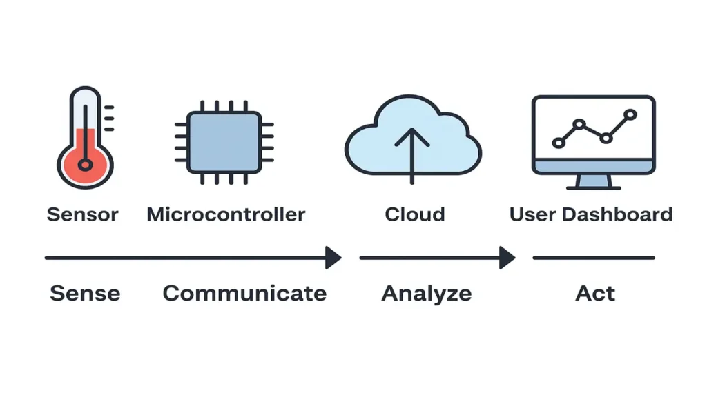
An IoT system therefore follows a sense → communicate → analyze → act loop.
Setting Up Your IoT Environment (Arduino & ESP32)
For beginners, Arduino UNO and ESP32 boards provide the easiest entry point into IoT hardware.
Tools Needed
- Arduino IDE (download from arduino.cc)
- USB cable
- DHT22 temperature sensor or LDR (light sensor)
- Jumper wires and breadboard
Setup Steps
- Install Arduino IDE and select your board type (Arduino UNO or ESP32).
- Connect the board via USB and verify port settings.
- Run a basic “Blink” sketch to ensure proper communication.
- Add libraries for your sensor (e.g., DHT sensor library).
- Upload the code and observe data in the Serial Monitor.
This establishes your first IoT data loop: sensor → microcontroller → PC dashboard.
Laboratory Exercise Blink and Read Sensor Data
Hardware Required
To perform this exercise, you’ll need the following components:
| Component | Description |
|---|---|
| Arduino UNO or ESP32 | The microcontroller that acts as the “brain” of your IoT system. |
| LED + 220 Ω resistor | Used to visualize device control (the LED will blink). |
| DHT22 Temperature Sensor | Measures temperature and humidity levels in your environment. |
| Jumper wires & Breadboard | For easy, reusable circuit connections. |
If you don’t have a DHT22, you can still complete the LED blinking part using just the Arduino board.
Step-by-Step Procedure
Step 1: Blink Test
Let’s start by making sure your board is working properly.
Open the Arduino IDE (or ESP32-compatible IDE) and upload the classic “Blink” sketch:
void setup() {
  pinMode(13, OUTPUT); // Set LED pin as output
}

void loop() {
  digitalWrite(13, HIGH); // Turn LED ON
  delay(1000);            // Wait 1 second
  digitalWrite(13, LOW);  // Turn LED OFF
  delay(1000);            // Wait 1 second
}
If your LED blinks every second, congratulations your microcontroller is alive and ready!
Step 2: Read Sensor Data
Now, connect the DHT22 sensor to your board:
- VCC → 5V
- GND → GND
- DATA → Pin 2 (or any digital pin)
Then install the DHT sensor library in Arduino IDE and use this sample code:
#include "DHT.h"
#define DHTPIN 2
#define DHTTYPE DHT22

DHT dht(DHTPIN, DHTTYPE);

void setup() {
  Serial.begin(9600);
  dht.begin();
}

void loop() {
  float temp = dht.readTemperature();
  float hum = dht.readHumidity();

  Serial.print("Temperature: ");
  Serial.print(temp);
  Serial.print(" °C | Humidity: ");
  Serial.print(hum);
  Serial.println(" %");

  delay(2000);
}
Open Serial Monitor (Tools → Serial Monitor) and you’ll see live temperature and humidity values updating every 2 seconds.
Step 3: Combine Both
Now let’s make your IoT device “think.”
We’ll modify the code so that the LED reacts to the sensor’s readings for example, if the temperature rises above 30°C, the LED will blink faster.
#include "DHT.h"
#define DHTPIN 2
#define DHTTYPE DHT22
#define LED 13

DHT dht(DHTPIN, DHTTYPE);

void setup() {
  pinMode(LED, OUTPUT);
  Serial.begin(9600);
  dht.begin();
}

void loop() {
  float temp = dht.readTemperature();

  Serial.print("Temperature: ");
  Serial.println(temp);

  if (temp > 30) {
    digitalWrite(LED, HIGH);
    delay(200);
    digitalWrite(LED, LOW);
    delay(200);
  } else {
    digitalWrite(LED, HIGH);
    delay(1000);
    digitalWrite(LED, LOW);
    delay(1000);
  }
}
Try breathing warm air onto the sensor you’ll see the LED blink faster as the temperature increases.
That’s your first real IoT feedback loop!
The approach followed at E Lectures reflects both academic depth and easy-to-understand explanations.
Summary and Next Steps
In this lecture, you explored:
- What IoT is and why it matters.
- Core concepts of IoT architecture.
- Step-by-step setup of an Arduino or ESP32 environment.
- Your first IoT lab task – controlling hardware and reading sensor data.
In the next lecture, you’ll delve into the IoT Architecture and TCP/IP Model, understanding how devices communicate across networks.
People also ask:
IoT stands for the Internet of Things a system of connected devices that collect and exchange data over the internet. These “things” can include sensors, appliances, or even vehicles that communicate automatically to make intelligent decisions.
IoT enables smarter homes, efficient industries, and safer cities. It reduces manual effort, improves decision-making, and connects technology to real-world data. From smart watches to connected cars IoT is shaping the future of automation.
An IoT system typically includes:
- Sensors/Actuators – to detect and act on physical changes.
- Microcontroller/Microprocessor – to process data (like Arduino or ESP32).
- Connectivity Module – for communication (Wi-Fi, Bluetooth, etc.).
- Cloud or Server – to store and analyze data.
- Application/Dashboard – where the user views or controls devices.
Arduino UNO is simple and great for beginners. It uses a USB connection and supports basic sensors.
ESP32 is more powerful, has built-in Wi-Fi and Bluetooth, and is better for advanced IoT projects that need wireless data exchange.
The lab helps you understand how a microcontroller can:
- Control an external component (the LED), and
- Read real-world data (from the DHT22 sensor).
Together, these steps show how IoT devices sense and respond to their surroundings.