
Microcontroller fundamentals through ESP32 architecture, I²C/SPI/UART communication, and FreeRTOS multitasking in IoT with real sensor lab exercises.
Introduction
Every IoT device is powered by a microcontroller a compact, low-cost computer that controls sensors, actuators, and data communication. In this lecture, you’ll explore how microcontrollers like the ESP32 manage multiple tasks using Real-Time Operating Systems (RTOS) such as FreeRTOS.
This forms the backbone of multitasking in IoT systems, enabling devices to sense, process, and communicate simultaneously.
What Is a Microcontroller?
A microcontroller (MCU) is an integrated circuit designed to perform specific tasks in embedded systems. It contains:
- CPU (Central Processing Unit) – Executes program instructions.
- Memory – Flash (program storage) and RAM (temporary data).
- I/O Pins – Interface for sensors, actuators, and communication.
- Peripherals – Built-in modules like timers, ADCs, UARTs, etc.
In IoT, microcontrollers act as the “brain” gathering sensor inputs, processing them, and triggering actions through actuators or network commands.
ESP32 Architecture Overview
The ESP32 is one of the most popular IoT microcontrollers due to its dual-core CPU, built-in Wi-Fi, and Bluetooth capabilities.
| Component | Description |
|---|---|
| CPU | Dual-core Xtensa LX6, up to 240 MHz |
| Memory | 520 KB SRAM, up to 16 MB external flash |
| Wireless | Wi-Fi 802.11 b/g/n, Bluetooth 4.2 |
| GPIO Pins | 34 programmable I/O pins |
| ADC/DAC | 12-bit ADC, 2-channel DAC |
| Interfaces | I²C, SPI, UART, PWM, CAN, Ethernet MAC |
| Power Modes | Deep Sleep, Light Sleep, Active |
This architecture allows parallel sensor reading, real-time data transmission, and efficient power management key for IoT applications.
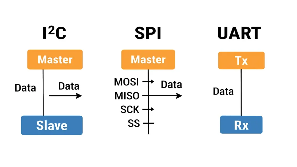
Communication Protocols (I²C, SPI, UART)
Microcontrollers use various communication protocols to exchange data with peripherals.
| Protocol | Type | Pins Required | Use Case |
|---|---|---|---|
| I²C (Inter-Integrated Circuit) | Serial (synchronous) | 2 (SDA, SCL) | Communicate with multiple low-speed sensors |
| SPI (Serial Peripheral Interface) | Serial (synchronous) | 4 (MISO, MOSI, SCK, SS) | High-speed data exchange with displays, memory chips |
| UART (Universal Asynchronous Receiver-Transmitter) | Serial (asynchronous) | 2 (TX, RX) | Communication between microcontrollers or PC |
Example:
- The ESP32 can connect an accelerometer (I²C), a display (SPI), and a serial terminal (UART) all at the same time.
Introduction to RTOS and FreeRTOS
A Real-Time Operating System (RTOS) allows multiple processes to run simultaneously, ensuring each task executes at the right time.
FreeRTOS (used in ESP32) is a lightweight RTOS ideal for IoT.
It manages:
- Task scheduling (deciding which task runs next)
- Inter-task communication (queues, semaphores)
- Delays and timers
- CPU core allocation
Why Use FreeRTOS?
- Makes code modular and easier to maintain.
- Enables multitasking (e.g., read sensors + transmit data + update display concurrently).
- Ensures predictable timing for critical tasks.
Lab Exercise – Reading Multiple Sensors Concurrently
Objective
To demonstrate multitasking by reading multiple sensors (DHT22 and Ultrasonic) at the same time using FreeRTOS tasks on ESP32.
Hardware
- ESP32 board
- DHT22 temperature & humidity sensor
- HC-SR04 ultrasonic sensor
- Jumper wires and breadboard
Step 1 – Setup Tasks in FreeRTOS
Each sensor will have its own task (thread).
#include <Arduino.h>
#include "DHT.h"
#define DHTPIN 4
#define DHTTYPE DHT22
DHT dht(DHTPIN, DHTTYPE);

// Ultrasonic pins
#define trigPin 5
#define echoPin 18

void readDHT(void *pvParameters) {
  while (1) {
    float temp = dht.readTemperature();
    float hum = dht.readHumidity();
    Serial.printf("Temp: %.2f °C  Humidity: %.2f %%\n", temp, hum);
    vTaskDelay(2000 / portTICK_PERIOD_MS);
  }
}

void readUltrasonic(void *pvParameters) {
  while (1) {
    digitalWrite(trigPin, LOW);
    delayMicroseconds(2);
    digitalWrite(trigPin, HIGH);
    delayMicroseconds(10);
    digitalWrite(trigPin, LOW);
    long duration = pulseIn(echoPin, HIGH);
    float distance = (duration * 0.034) / 2;
    Serial.printf("Distance: %.2f cm\n", distance);
    vTaskDelay(1500 / portTICK_PERIOD_MS);
  }
}

void setup() {
  Serial.begin(115200);
  dht.begin();
  pinMode(trigPin, OUTPUT);
  pinMode(echoPin, INPUT);
  xTaskCreate(readDHT, "DHT Task", 2048, NULL, 1, NULL);
  xTaskCreate(readUltrasonic, "Ultrasonic Task", 2048, NULL, 1, NULL);
}

void loop() {}
Result:
Both sensors send data to the Serial Monitor independently and simultaneously, demonstrating concurrent execution.
Step 2 – Observe Task Scheduling
- DHT task updates every 2 seconds
- Ultrasonic task updates every 1.5 seconds
- The ESP32 alternates smoothly between tasks without lag.
The approach followed at E Lectures reflects both academic depth and easy-to-understand explanations.
Summary
After this lecture, you will be able to:
- Explain microcontroller architecture and its components.
- Use I²C, SPI, and UART interfaces for IoT communication.
- Implement FreeRTOS multitasking for concurrent sensor operations.
- Understand how task scheduling enhances IoT performance.
People also ask:
A microcontroller is a compact computer on a single chip that controls electronic devices. It contains a processor (CPU), memory, and input/output ports to interact with sensors, actuators, and other components. It is the “brain” of most IoT systems.
A microcontroller is designed for specific tasks and includes CPU, memory, and peripherals in one chip (e.g., ESP32, Arduino).
A microprocessor focuses on general-purpose computing and requires external memory and I/O modules (e.g., Intel i5, Raspberry Pi CPU).
The ESP32 is ideal for IoT because it has:
- Built-in Wi-Fi and Bluetooth connectivity.
- Dual-core processor for multitasking.
- Support for FreeRTOS for real-time control.
- Multiple communication interfaces (I²C, SPI, UART).
- Low power modes for battery-based devices.
Communication protocols allow devices and sensors to exchange data reliably.
- I²C: Two-wire protocol for multiple low-speed sensors.
- SPI: Fast protocol for high-speed devices like displays or SD cards.
- UART: Simple serial communication, often used for debugging or PC connection.
RTOS stands for Real-Time Operating System. It manages multiple tasks by ensuring each runs at the correct time, providing predictable and reliable performance critical in systems like IoT, robotics, or automotive devices.