Combinational Circuits in Digital Logic Design: Definition, Types, Examples & Comparison with Sequential Circuits

Learn combinational circuits in Digital Logic Design with clear definitions, differences from sequential circuits, types, explained diagrams, real-world applications, and step-by-step examples. Ideal for BS students.
Introduction
Digital systems are everywhere from smartphones and laptops to traffic lights and medical equipment. At the heart of these systems lie digital logic circuits, which process information in binary form (0s and 1s). Understanding these circuits is essential for students of Computer Science, Electrical Engineering, and Artificial Intelligence.
This lecture focuses on combinational circuits, their definition, working principle, types, and real-world usage. Before diving into combinational circuits, we first distinguish them clearly from sequential circuits, as both are fundamental pillars of digital logic design.
What Is a Digital Logic Circuit?
A digital logic circuit is an electronic circuit that processes digital signals using logic gates such as AND, OR, NOT, NAND, NOR, XOR, and XNOR. These circuits operate on binary inputs and generate binary outputs based on logical rules.
Digital logic circuits are divided into two major categories:
- Combinational Circuits
- Sequential Circuits
Difference Between Combinational and Sequential Circuits
Understanding this difference is critical before moving forward.
| Feature | Combinational Circuits | Sequential Circuits |
|---|---|---|
| Output depends on | Present input only | Present input + past output |
| Memory | No memory | Uses memory |
| Feedback | No feedback path | Feedback present |
| Clock signal | Not required | Usually required |
| Speed | Faster | Slower due to clock |
| Examples | Adders, MUX | Flip-flops, Counters |
Simple Explanation
- Combinational circuit: Like a calculator → press buttons, get result immediately
- Sequential circuit: Like a stopwatch → output depends on previous state
Definition of Combinational Circuit
A combinational circuit is a type of digital circuit in which the output depends only on the current input values, without any memory or storage element.
Mathematically:
Output = f(Current Inputs)
There is no clock, no feedback, and no history dependency.
Key Characteristics of Combinational Circuits
- No memory elements
- No clock signal
- Fast response
- Easy to design
- Output changes immediately with input
- Built using logic gates only
Types of Combinational Circuits
Combinational circuits are classified based on their function:
- Arithmetic Circuits
- Data Routing Circuits
- Code Converter Circuits
- Comparator Circuits
Each type is explained below with two examples, step-by-step logic, and real-world usage.
1. Arithmetic Circuits
Arithmetic circuits perform mathematical operations such as addition and subtraction.
Example 1: Half Adder

A Half Adder adds two single-bit binary numbers.
Inputs: A, B
Outputs:
- Sum = A ⊕ B
- Carry = A · B
Step-by-Step Explanation
- If A = 0, B = 0 → Sum = 0, Carry = 0
- If A = 1, B = 0 → Sum = 1, Carry = 0
- If A = 1, B = 1 → Sum = 0, Carry = 1
Real-World Use
- Basic arithmetic units
- Teaching foundation for addition logic
Example 2: Full Adder
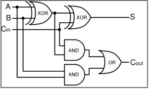
A Full Adder adds three inputs: A, B, and Carry-in.
Outputs:
- Sum = A ⊕ B ⊕ Cin
- Carry = AB + ACin + BCin
Step-by-Step Framework
- Add A and B
- Add Carry-in
- Generate Sum and Carry
Real-World Use
- CPUs
- ALUs
- Multi-bit adders
2. Data Routing Circuits
These circuits control data flow and selection.
Example 1: Multiplexer (MUX)
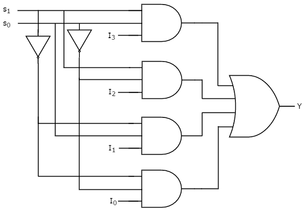
A Multiplexer selects one input from many and forwards it to the output.
Step-by-Step Working
- Select lines decide which input is passed
- Only one input is active at a time
Real-World Use
- Communication systems
- CPU instruction selection
- Data buses
Example 2: Demultiplexer (DEMUX)
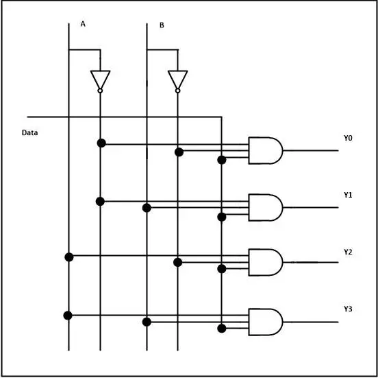
A Demultiplexer distributes one input to multiple outputs.
Real-World Use
- Data distribution
- Memory systems
- Signal routing
3. Code Converter Circuits
Used to convert data from one format to another.
Example 1: Binary to Gray Code Converter
Why Gray Code?
- Only one bit changes at a time
- Reduces error in transitions
Real-World Use
- Rotary encoders
- Communication systems
Example 2: BCD to 7-Segment Decoder
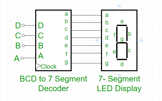
Real-World Use
- Digital clocks
- Calculators
- Display units
4. Comparator Circuits
Comparator circuits compare binary numbers.
Example 1: 1-Bit Comparator
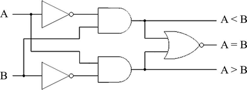
Outputs indicate:
- A > B
- A < B
- A = B
Example 2: 4-Bit Comparator
Real-World Use
- CPUs
- Sorting circuits
- Control systems
Summary
Combinational circuits are the foundation of digital systems. They are fast, efficient, and easy to design because they depend only on current inputs. From simple adders to complex data routing systems, combinational circuits play a vital role in modern electronics.
Before moving to sequential circuits, mastering combinational logic is essential for:
- CPU design
- Embedded systems
- AI hardware understanding