Boolean Algebra and Logic Gates in Digital Logic Design 2025
Boolean Algebra and Logic Gates
Learn Boolean Algebra and Logic Gates in Digital Logic Design a complete, step-by-step explanation with truth tables, circuit examples, and practical applications. Ideal for students and teachers in AI and computer science.
Introduction to Boolean Algebra and Logic Gates
Boolean Algebra and Logic Gates form the backbone of Digital Logic Design (DLD) the study of how computers make logical decisions using binary (0s and 1s).
Boolean Algebra provides the mathematical foundation, and Logic Gates are the hardware implementation.
Definition of Boolean Algebra
Boolean Algebra is a mathematical system that operates on binary variables (0 and 1).
It was introduced by George Boole, and later applied to electrical circuits by Claude Shannon.
For a deeper understanding of how logical circuits form the foundation of computing and AI, visit our post on Digital Logic Design _ Number Systems
Boolean Operations and Truth Tables
| Operation | Symbol | Expression | Meaning | Example |
|---|---|---|---|---|
| AND | · | A·B | True only if both A and B are True | 1·1 = 1 |
| OR | + | A + B | True if any input is True | 1+0 = 1 |
| NOT | ¬ or ̅ | ¬A | Inverts the input | ¬1 = 0 |
Extended operations: NAND, NOR, XOR, XNOR — all based on Boolean principles.
o explore how data is stored, organized, and managed efficiently in programming, check out our detailed article on Introduction to Data Structures (2025)
Boolean Laws and Theorems
| Law | Expression | Description |
|---|---|---|
| Commutative | A+B=B+A | Order doesn’t matter |
| Associative | (A+B)+C=A+(B+C) | Grouping doesn’t affect result |
| Distributive | A·(B+C)=A·B+A·C | AND distributes over OR |
| Identity | A+0=A, A·1=A | Identity elements |
| Complement | A+Ā=1, A·Ā=0 | A variable + complement = 1 |
| De Morgan’s | ¬(A·B)=¬A+¬B, ¬(A+B)=¬A·¬B | Convert between AND/OR |
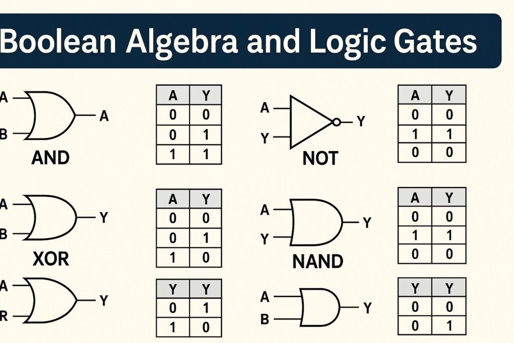
Logic Gates Explained
Logic Gates are the physical circuits that perform Boolean operations.
They have inputs (binary signals) and one output.
Basic Logic Gates
| Gate | Symbol | Operation | Output Description |
|---|---|---|---|
| AND | A·B | Logical multiplication | Output is 1 if both inputs are 1 |
| OR | A+B | Logical addition | Output is 1 if any input is 1 |
| NOT | ¬A | Inverter | Output is opposite of input |
Universal Logic Gates
| Gate | Operation | Description |
|---|---|---|
| NAND | ¬(A·B) | Opposite of AND; used to build all circuits |
| NOR | ¬(A+B) | Opposite of OR; universal gate |
Special Gates
| Gate | Expression | Use |
|---|---|---|
| XOR | A⊕B | 1 if inputs differ (used in adders) |
| XNOR | ¬(A⊕B) | 1 if inputs are same (used in comparators) |
Learn how the evolution of digital logic and binary systems paved the way for modern security mechanisms in our insightful post on the History of Cybersecurity
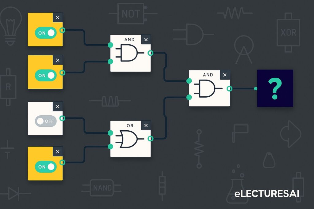
Relationship Between Boolean Algebra and Logic Gates
- Boolean equations are implemented using logic gates.
- Example: F=A⋅B+C‾F = A·B + \overline{C}F=A⋅B+C → represented by an AND-OR-NOT circuit.
Example
Summary Table
| Concept | Symbol | Use |
|---|---|---|
| Boolean Algebra | +, ·, ¬ | Mathematical logic |
| Logic Gates | AND, OR, NOT | Circuit implementation |
| Universal Gates | NAND, NOR | Build all logic functions |
| Special Gates | XOR, XNOR | Used in adders and comparators |
Fun Memory Lines for Class
- “AND demands all ON, OR opens with one ON.”
- “NAND and NOR are rebels they flip the rules.”
- “XOR explores differences, XNOR loves equality.”
- “De Morgan breaks the bar, flips the star.”
- “Complement completes the circuit!”